The 8051 or the AT89C51 is an 8-bit microcontroller. The 8051 microcontroller was designed long ago by Intel. It has a 40 pin DIP – Dual Inline Package. It has 4 kilobytes of ROM, 128 bytes of ram, two internal timers, and 5 interrupts. Namely, INT0, TF0, INT1, TF1 and RI/TI. The order of priority is same as the order they are written. It also has 1 non-maskable interrupt – RESET.
There are 2 timers available in the 8051. The timer0 and the timer1, and there are 4 modes in which both of these timers can be configured. And each of it can be configured as a Timer or as a Counter.
Difference between timers and counters
Timer in 8051 is used to provide timing or delays between two events in the controller. Whereas, a counter is used to count the number of events. The TMOD or
the Timer MOD register, which is a byte addressable register, is used to configure the timer/counter.
Consider the TMOD register
as shown below. The 0th and the 1st bit is used to configure the modes for timer0, and the 4th and 5th bit for timer1.
The 2nd and the 6th bit is used for configuring it in either timer mode or counter mode for timer0 and timer1 respectively. If the 2nd/6th bit is 0, its configured as timer, else it’s in counter mode.

- Gate: The gate bit decides whether the timer is controlled – RUN or STOP, with the internal interrupts, TR0 and TR1 or the external ones – INT0 & INT1.
- C/T: This bit decides whether to operate in timer mode or in counter mode
- M0, M1: These bits decides the mode of operation of the timers.
Timer modes in 8051
There are 4 timer modes in the 8051 microcontroller.
- Mode 0
Mode 0 is a 13-bit timer/counter. All the 8 bits from the upper byte are used with 5 most significant bit from the lower byte. Timer in this mode can be used by status check method. Maximum delay in this mode is 8.8 millisecond at a crystal frequency of 11.0592 MHz. - Mode 1
When using mode 1, the timer/counter is configured in 16-bit mode. To be specific, it’s counts all the way from 0x0000 to 0xffff. And this mode gives a maximum delay of 71.106 millisecond, again at a crystal frequency of 11.0592 MHz. - Mode 2
In mode 2 configuration, the timer/counter works in 8 bit mode but has a special feature this time. It has auto reload capacity. Meaning that, it can run continuously, all on its own, reloading the timer with the value stored in the higher byte. This mode is usually used for setting the baud rate for serial communication. - Mode 3
Mode 3 is a split mode where in the timer or counter operates in the 8-bit mode. The TL0 uses the timer flag TF0, where as the TH0 uses the timer flag TF1. Yes, its timer0 using flags of both timer0 and timer1.
The concept of delays and timers
Now that you know the basic working of the timers in the 8051 microcontroller, let’s go through the concept of delays.
Delays are nothing but the cycles of operation with in the controller where the controller
does nothing, literally nothing. If you know any programming language, its similar to a for or while loop that does nothing.
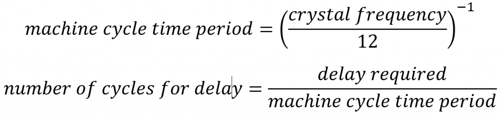
The most common clock frequency in the 8051 is 11.0592 MHz. The main reason to use this frequency is it compatibility with the most common baud rates in serial communication. Now, this clock frequency will give us a machine cycle time period of 1.085 microsecond. For a delay of 1 second, we need 921600 machine cycles.
We will be using timer0 in mode 1 configuration. Since it’s a 16-bit timer the maximum delay will be 71.11 millisecond. So, we need to run the timer for 14 complete cycles + 4096 machine cycles. I’ll leave the calculations to you.
So, now that we are done with the theory. Let’s have a look at the code.
The Assembly Code
				org 0000h
					mov p1, #00h
					mov tmod, #01h
loop:				cpl p1.5    ;compliment pin 1.5
					acall delay
					acall smallDelay
					sjmp loop

;the subroutine delay is to loop for 14 complete 16-bit timer cycles
;and the subroutine smallDelay is for looing for 4096 times.
;the rest of the code is self explainatory.

delay:				mov r0, #14
					mov tl0, #00h
					mov th0, #00h
					setb tr0
timerLoop:			jnb tf0, timerLoop
					clr tf0
					djnz r0, timerLoop
					clr tr0
					ret

smallDelay:			mov tl0, #00h
					mov th0, #0f0h
					setb tr0
timerLoop2:			jnb tf0, timerLoop2
					clr tr0
					clr tf0
					ret

					end
Download the code from here.
This code will result
in toggling of pin 1.5 every second, only if operating at 11.0592 MHz. The C-equivalent code for the same program is also geven.
The embedded C Code | 8051 timer programming in C
#include<reg51.h>

sbit pin = P1^5;

void delay(){
    int i;
    TMOD = 0x01;
    for(i=0; i<1000; i++){
				TH0 = 0xFC;
				TL0 = 0x66;
				TR0 = 1;
        while(TF0 != 1){
            ;
        }
				TR0 = 0;
        TF0 = 0;
    }
}

void main(){
    while (1)
    {
        pin = ~pin;
        delay();
    }

}
Download this code from my Github.
That completes the
part of toggling any pin with a delay of exactly 1 second.
Read more posts on 8051 from here.
FAQs
How do I change the pin that has to be toggled?
You can do that by simply changing the line cpl p1.5 or the line sbit pin = P1^5; in embedded C to the required pin. You can also modify the code to toggle an entire port instead
of a single pin.
What’s the difference between a Timer and a Counter?
I suggest you read this again.
How do I change the time for toggling?
Simply change the delay function, by changing the value in the TH0 and TL0.
What are the different timer/counter modes in 8051
Read about timer/counter modes from here.