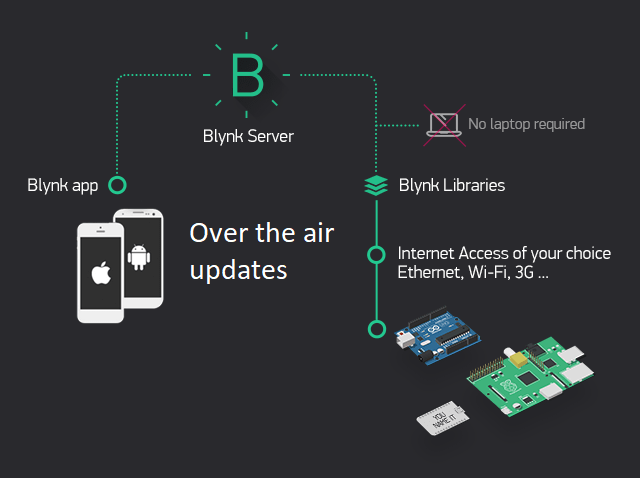
We all know that the Blynk app together with tiny micro controllers is an amazing combination for IoT. NodeMCU, ESP8266, ESP32 and many other Arduino boards are compatible with the Blynk platform. With such large support, Blynk OTA would be a over whelming feature. The code uploading and testing of the device is simple when in the prototype stage. But, when you have a completed the design and development and have no access to the serial port over the USB, you can no longer upload new codes and updates to the devices without breaking them apart.
But is it possible to have the Blynk code updated the over the air (OTA)?
Well officially, the Blynk Platform doesn’t support the OTA updates. They do have it, but with “0” compatibility, making it of no use. They might develop it in the future, but the wait is never over.
Don’t have Arduino IDE, download Arduino IDE from their official website.
The solution for Blynk OTA over WiFi
Do you know that the Arduino OTA library, helps in uploading the code to any device over the network. Well if you don’t. Yeah, it does, using the TCP/IP protocol.
The Arduino OTA code
#include <ESP8266WiFi.h>
#include <ESP8266mDNS.h>
#include <WiFiUdp.h>
#include <ArduinoOTA.h>
#ifndef STASSID
#define STASSID "your-ssid" //put your WiFi SSID (Name)
#define STAPSK "your-password" //Set your WiFi Password
#endif
const char* ssid = STASSID;
const char* password = STAPSK;
void yourSetup(){
//put your code that need to run once
}
void yourLoop(){
//put the code that needs to run continuously
}
void setup() {
Serial.begin(115200);
Serial.println("Booting");
WiFi.mode(WIFI_STA);
WiFi.begin(ssid, password);
while (WiFi.waitForConnectResult() != WL_CONNECTED) {
Serial.println("Connection Failed! Rebooting...");
delay(5000);
ESP.restart();
}
// Port defaults to 8266
// ArduinoOTA.setPort(8266);
// Hostname defaults to esp8266-[ChipID]
// ArduinoOTA.setHostname("myesp8266");
// No authentication by default
// ArduinoOTA.setPassword("admin");
// Password can be set with it's md5 value as well
// MD5(admin) = 21232f297a57a5a743894a0e4a801fc3
// ArduinoOTA.setPasswordHash("21232f297a57a5a743894a0e4a801fc3");
ArduinoOTA.onStart([]() {
String type;
if (ArduinoOTA.getCommand() == U_FLASH) {
type = "sketch";
} else { // U_FS
type = "filesystem";
}
// NOTE: if updating FS this would be the place to unmount FS using FS.end()
Serial.println("Start updating " + type);
});
ArduinoOTA.onEnd([]() {
Serial.println("\nEnd");
});
ArduinoOTA.onProgress([](unsigned int progress, unsigned int total) {
Serial.printf("Progress: %u%%\r", (progress / (total / 100)));
});
ArduinoOTA.onError([](ota_error_t error) {
Serial.printf("Error[%u]: ", error);
if (error == OTA_AUTH_ERROR) {
Serial.println("Auth Failed");
} else if (error == OTA_BEGIN_ERROR) {
Serial.println("Begin Failed");
} else if (error == OTA_CONNECT_ERROR) {
Serial.println("Connect Failed");
} else if (error == OTA_RECEIVE_ERROR) {
Serial.println("Receive Failed");
} else if (error == OTA_END_ERROR) {
Serial.println("End Failed");
}
});
ArduinoOTA.begin();
Serial.println("Ready");
Serial.print("IP address: ");
Serial.println(WiFi.localIP());
yourSetup();
}
void loop() {
ArduinoOTA.handle();
yourLoop();
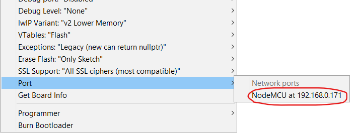
}The code is exactly same as provided in the examples in the Arduino IDE with slight modification, it’s simple and easy to understand. Once uploaded to your NodeMCU or any ESP, your device’s network port will show up in the Arduino IDE as below.
What’s next? Adding Blynk code to the OTA code.
You can see there are 2 functions at the starting of the code. This is where your main program code will be. The functions void yourSetup() and void yourLoop() will word just like the void loop() and the void setup() functions.
void yourSetup(){
  //put your code that need to run once
}

void yourLoop(){
  //put the code that needs to run continuously
}
Now we need to add the Blynk code. First we need to import the Blynk header file, then add the credentials, and then copy paste the Blynk setup and loop’s code into our setup and loop. The complete code is given below.
#include <ESP8266WiFi.h>
#include <WiFiUdp.h>
#include <ArduinoOTA.h>

#include <BlynkSimpleEsp8266.h>
char auth[] = "Your_auth_token_here";

#ifndef STASSID
#define STASSID "Your_WiFi_SSID_here"
#define STAPSK "Your_WiFi_Password_here"
#endif

const char *ssid = STASSID;
const char *password = STAPSK;

void yourSetup()
{
  Blynk.begin(auth, ssid, password);
}

void yourLoop()
{
  Blynk.run();
}

void setup()
{
  Serial.begin(115200);
  Serial.println("Booting");
  WiFi.mode(WIFI_STA);
  WiFi.begin(ssid, password);
  while (WiFi.waitForConnectResult() != WL_CONNECTED)
  {
    Serial.println("Connection Failed! Rebooting...");
    delay(5000);
    ESP.restart();
  }

  ArduinoOTA.setHostname("NodeMCU");

  ArduinoOTA.onStart([]() {
    String type;
    if (ArduinoOTA.getCommand() == U_FLASH)
    {
      type = "sketch";
    }
    else
    { // U_FS
      type = "filesystem";
    }

    // NOTE: if updating FS this would be the place to unmount FS using FS.end()
    Serial.println("Start updating " + type);
  });
  ArduinoOTA.onEnd([]() {
    Serial.println("\nEnd");
  });
  ArduinoOTA.onProgress([](unsigned int progress, unsigned int total) {
    Serial.printf("Progress: %u%%\r", (progress / (total / 100)));
  });
  ArduinoOTA.onError([](ota_error_t error) {
    Serial.printf("Error[%u]: ", error);
    if (error == OTA_AUTH_ERROR)
    {
      Serial.println("Auth Failed");
    }
    else if (error == OTA_BEGIN_ERROR)
    {
      Serial.println("Begin Failed");
    }
    else if (error == OTA_CONNECT_ERROR)
    {
      Serial.println("Connect Failed");
    }
    else if (error == OTA_RECEIVE_ERROR)
    {
      Serial.println("Receive Failed");
    }
    else if (error == OTA_END_ERROR)
    {
      Serial.println("End Failed");
    }
  });
  ArduinoOTA.begin();
  Serial.println("Ready");
  Serial.print("IP address: ");
  Serial.println(WiFi.localIP());
  yourSetup();
}

void loop()
{
  ArduinoOTA.handle();
  yourLoop();
}
That’s it, you now have your Blynk code running on your edge device with OTA – Over The Air updates capability. Add or remove or manipulate the code in the yourSetup and the yourLoop part, you will have your OTA capability.
Having problem uploading the code? check out the FAQs
My network port is not showing up on the Arduino IDE
The Arduino IDE does have a problem detecting and working with the network ports. If your code is uploaded and the device is connected to WiFi and the network port is not being shown, restart your IDE.
If the port is not being shown even after restarting, I suggest you to shift over to PlatformIO on Visual Studio Code for micro controller programming. It has a lot better coding and debugging experience. Or check out this post if you want to setup your own custom Blynk server.
Blynk OTA
The most simple, easy to use and 100% working OTA code for Blynk with NodeMCU, ESP8266, ESP32 and so on.
Operating System: Windows 10, Linux, Mac OS, OSX
Application Category: IoT, Arduino