In order to generate a square wave using 8051 or in otherwords the AT89C51, we will be using proteus. Its a software used to simulate the project. We will also need a DAC, a Digital to Analog Converter in short, and the AT89C51 microcontroller itself.
The DAC we will be using is a simple DAC0808. Its a 16 pin DIP package and easy to use.
The 8051 has two timers which can be configured in 3 modes. We will not be using the timers for the delay but instead the software delays to produce an approxiamate delay.
Steps to generate a square wave using 8051
- Set the output of any port on the 8051 to logic high.
- Wait for some time.
- Set the output of the same port to logic low.
- Again wait for the same amount of time as you did earlier.
- Loop around the same.
Subsequently, for obtaining the desired frequency on the square wave. We have to manipulate with the delay. We know that the machine cycle frequency is 1/12 of the crystal oscillator frequency. So, with the crystal oscillator’s frequency as 11.0592 Mhz the machine cycle frequency is 921.6 Khz. To sum up, thats equivalent to 1.085 μsecond.
To generate a square wave of 1 KHz, in other words, a wave of time period 1 millisecond, we have to use the delay in such a way that it causes a delay of 1 millisecond. We will have to loop around doing nothing for about 461 machine cyclesto generate a square wave of 50% duty cycle. That is to say, an on time and an off time of 0.5 millisecond.
Now, since we know the logic behind the generation of square wave, we can work on the hardware.
The Hardware
One of the major mistake people do is to write the code first and then build the hardware. Thats ok when you are simulating or building a mini project. But in the long run, when you are working on big projects, starting on with the hardware is the best way to do it.
So, lets build the hardware. The components that we are using are as follows
- The AT89C51 μcontroller.
- DAC0808.
- Resistors.
- Capacitors.
- An opamp – the DAC0808 output is known current. The opamp is to convert it to known voltage.
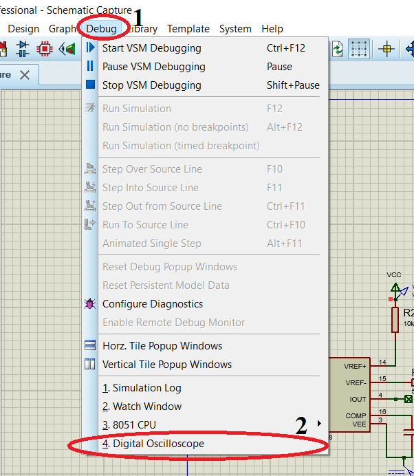
- CRO to visualize the wave.
The Placements and Connections
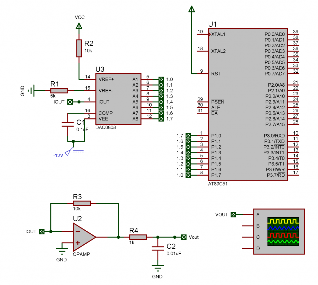
Firstly, place the μcontroller and the DAC0808 IC from the libraries in Proteus workspace. Connect the reset pin to the power source (Vcc). We will be connecting the DAC0808’s data pins to the port 1 of the μcontroller. Make sure you are connecting the MSB bit to the A1 pin (pin number 5) on DAC0808 and the LSB pin to the A8 pin (pin 12 physically). To avoid any confusions, follow the schematic below.
The code to generate a square wave using 8051
Lets start off with the line. Since we need the wave to start from logic 0, we pass on the data 00h to port 1.
org 0000h
mov a, #00h
mov p1, a
Next, we need to add some delay so that we get a constant high DC voltage – logic high. We do it by defining a function or sub-routine called as delay.
acall delaydelay: mov r1, #0ffh
loop2: mov r0, #0ah
loop: djnz r0, loop
djnz r1, loop2
retThen we need to send logic high to the DAC connected to port 1, and then call the delay sub-routine again.
mov a, #0ffh
mov p1, a
acall delay
Now that we have created the first wave. We need to loop the program so that it keeps on running as long as the μcontroller is on. So we loop it by using the SJMP command.
sjmp startOverand also add a lebel at the beginning of the code. So, replace
mov a, #00hwith
startOver:mov a, #00hor any other label name you used.
Need the complete code file..? Get it from my GitHub repo here.
Compilation
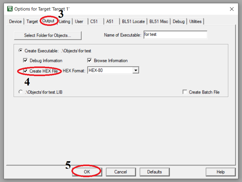
Further, we need to compile the code written. I for instance prefer compiling in Keil μVision because i am more familiar with it, you can use any other compiler. Make sure your option to generate hex file is enabled, as shown below.
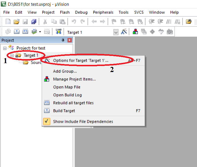
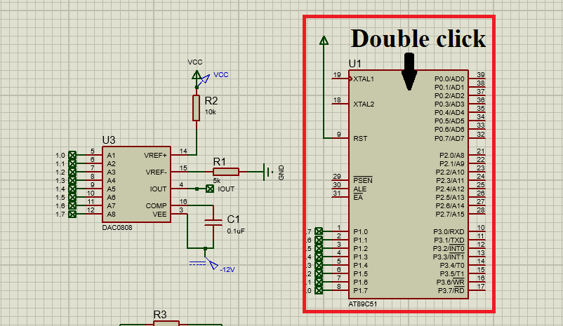
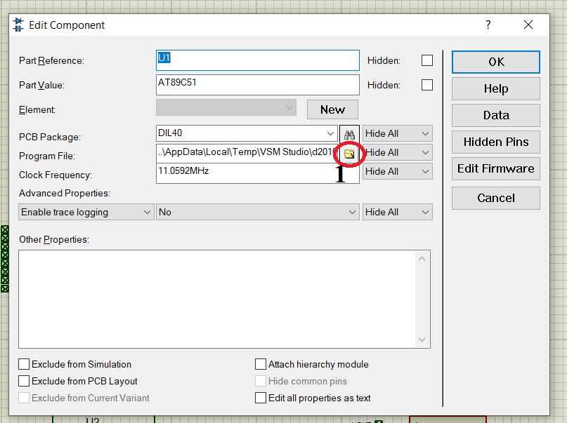
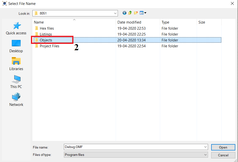
Subsequently, open your Proteus File and double Click the μcontroller, you should see a pop-up window asking you to select the debug file. You should select the hex file, it is usually placed in the Objects folder in your keil project folder.
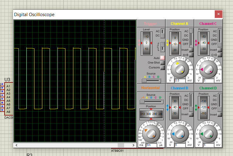
To sum up, you have just learnt how to generate a square wave using 8051 μcontroller. And also simulated it in proteus. Well, congratulation on that. So if you have any doubts, drop them in the comments section.
Care to Share? Check out my other posts here.