In this post you will learn how to interface seven segment display with the 8051 microcontroller (AT89C51) in multiplexed method, alternatively rolling seven segment display in a simulation software called Proteus.
The basic concept behind multiplexed seven segment display is to turn on one display at a time, at a rate so fast that it seems to our eyes that all of the displays are turned on. I will be using 8 such displays and show you how to use them in the right way.
Introduction to seven segment display
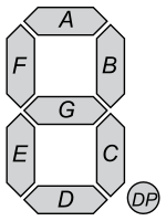
As it can be seen from the picture beside that the digit 8 is made up of 7 segments which can be indivisually turned on or off to display a character. Also, make a note that it can be used to display all the numbers, but not all the letters. For instance, letters like Z, N, G, J, K, M, Q, R, and so on can’t be displayed. While letters like O, B, D cause a lot of confusion when interpreting.
The displays can be used in 2 modes or 2 configurations.
1. Common Anode (common +ve terminal)
2. Common Cathode (common ground)
We will be using the 2nd one, the common cathode or
the common ground because it causes less confusions in logics.
We will be using the entire 8 bit port. So we have to connect led A to the MSB, led B to next LSB and so on up till the last one. This will make the led G connect to the last but one bit. The last bit will have to be connected to the DP, or the point.
So inorder to display the letter A, you must turn on led E, F, A, B, C, G and turn off the rest. That combination would give us 11101110 in binary that has to be sent to the required port. Like wise, to display the letter E, would have to send 10011110 in binary to the required port. This covers the basics.
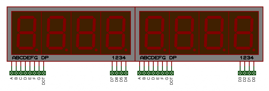
The Hardware
Indeed the first thing you need to do is to set up the hardware. Connect the seven segment displays as shown in the schematic. If you have indivisual displays and not blocks of them. Just connect them in parallel and then connect them to the microcontroller.

The assembly code
In order to use the seven segment display, we need to use the lookup table method. Lookup table method is a way to access the data based on the addresses or in programming terminology, the indexed. So we will write the table starting from location 500h on the ROM as follows.
org 500h
numbers: db 11111100b, 01100000b, 11011010b, 11110010b, 01100110b, 10110110b, 10111110b, 11100000b, 11111110b, 11110110b
_H: db 01101110b
_E: db 10011110b
_L: db 00011100b
_O: db 11111100b
_A: db 11101110b
_F: db 10001110b
_Z: db 11011010b
_C: db 10011100B
_: db 00000001b
The 1st bit from the right, in other words, the LSB, corresponds to the point (DP) led on the seven segment display. So sending the value 00000001b to the displays will turn on the point. The MSB bit corresponds to the segment A, the next bit to B, the next one to C and so on up to G.
The main program
org 0000h
mov p1, #0ffh
mov p2, #00h
Port 1 is set to turn off all the displays, and Port 2 is cleared to configure it as output port.
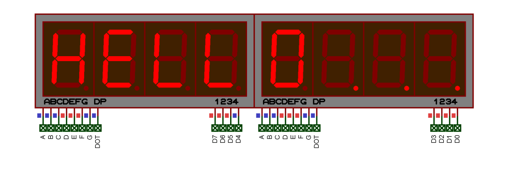
startOver:mov dptr, #_H
acall display1
mov dptr, #_E
acall display2
mov dptr, #_L
acall display3
mov dptr, #_L
acall display4
mov dptr, #_O
acall display5
mov dptr, #_
acall display6
mov dptr, #_
acall display7
mov dptr, #_
acall display8
sjmp startOver
the command mov dptr, #_H loads the hex value of code from the lookup table. Since we have used 8 displays in multiplexed mode, the subroutine acall display1 send the data to 1st display and turns the display ON for some time and then turns it OFF. Similarly, acall display2 sends the data to 2nd display, turns it ON for some time and then turns it OFF. The rest of the commands similar to acall display* send the data to corresponding display, turns it ON for some time and then turns it OFF again.
Since this process is repeated at a very high rate, our eyes perceives them as if all the displays are turned ON simultainously.
acall routine:clr a
movc a, @a+dptr
mov p2, a
acall lessDelay                   ;CAN BE OMITTED
ret

display1:clr p1.7
acall routine
setb p1.7
ret

display2:clr p1.6
acall routine
setb p1.6
ret

display3:clr p1.5
acall routine
setb p1.5
ret

display4:clr p1.4
acall routine
setb p1.4
ret

display5:clr p1.3
acall routine
setb p1.3
ret

display6:clr p1.2
acall routine
setb p1.2
ret

display7:clr p1.1
acall routine
setb p1.1
ret

display8:clr p1.0
acall routine
setb p1.0
ret
Now the delay function is as follows. You can omit the delay part if you want
lessDelay:mov r0, #0fh
loop5:mov r1, #127
loop4:djnz r1, loop4
djnz r0, loop5
ret
Download the assembly language codes, .asm file as well as the Proteus file from here.
You can customize the code and workaround to have your content displayed.
Visit my github  page for more codes like this.
Intrested in creating a website for free ? Or setting up your own Blynk server for IoT ?
Care to share.😄